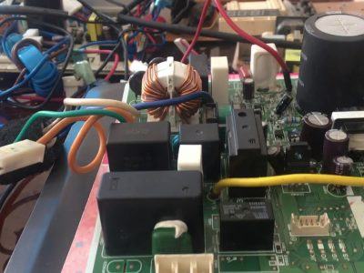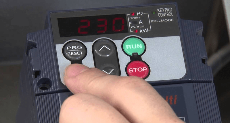
Mitsubishi inverters on the market today are the most commonly used lines such as: Mitsubishi inverter FR-A720, FR-A500, E500, Mitsubishi inverter FR-V500, Inverter FR-A700, FR-D700, FR- E700, FR-A800, FR-F800… In the repair process with code FR-A720, there are common errors such as:
1. Output phase loss error
– Check wiring, motor to see if installed properly
– Make sure the power of the motor used is not less than the capacity of the inverter
2. Input phase loss error
– Check the cable connection
– Check the Pr setting. 872 to select input phase loss protection
3. Overcurrent interrupt during acceleration
– When the output current of the FR-A720 inverter reaches or exceeds 220% of the rated current during acceleration, the protection circuit will be activated to stop the inverter output. Proceed to increase the acceleration time. When “E.OC1” is on at startup, disconnect the motor, then restart the inverter. If “E.OC1” is still lit, contact technician for advice
– Check the wiring to make sure there is no output short circuit. Reset Pr. 3 base frequency about 50Hz.
– Check the connection of the RS-485 terminal block. Make sure the motor does not change the direction of rotation from forward to reverse
4. Overcurrent error
– Increase or decrease Pr. 0 to 1% and check the motor status
– Set a larger value in Pr. 7 and Pr. 8
– Reduce the weight of the load.
– Try early magnetic line vector control, sensorless real vector control or vector control.
– Change the Pr setting. 14
– Set operating current for stall protection in Pr. 22
– Change acceleration/deceleration time. Proceed to increase stall protection operation level with Pr. 22 or disable stall protection with Pr. 156.
5. PU disconnect error
Carry out re-check, install FR-DU07 or parameter device (FR-PU04/FR-PU07) permanently.
6. Breaking regenerative overvoltage during acceleration
– If the regenerative energy causes the main circuit DC voltage of the inverter to reach or exceed the specified value, the protection circuit will be activated to stop the output of the inverter. Alternatively, the circuit can be activated by the pulse voltage generated in the power supply system.
– Reduce acceleration time, Use regeneration avoidance function (Pr. 882 to Pr. 886), Set a value larger than no-load current in Pr. 22
7. CPU error
– Stop the output of the inverter if a transmission error of the built-in CPU occurs.
– Take anti-interference measures if there are devices causing excessive electromagnetic interference around the inverter installation location.
Contact technical for advice
8. Analog input error
– Stops the output of the inverter when a current of 30mA or more or a voltage of 7.5V or more enters terminal 2, while selecting the current input by Pr. 73 or to terminal 4 and input current with Pr. 267
– Send frequency control command by current input or Pr setting. 73, Pr. 267 switches the voltage/current input to the voltage input.
9. USB transmission error
– When the time set in Pr. 548 has been tripped, this function will stop the output of the inverter.
– Check the Pr setting. 548, test USB transmission.
– Check the USB transmission cable.
– Increase the Pr setting. 548 or change the setting to 9999.
10. Encoder phase error
– Disconnect the inverter when the rotation control command of the motor is different from the actual rotation direction of the motor detected from the encoder. This error is not usually present in the initial state.
– Make sure the connection and wiring are done. Change, set Pr values. 35
Contact us: GL Commerce Co., Ltd
Address: Thien Ke Hamlet, Thien Ke Commune, Binh Xuyen District, Vinh Phuc Province
Hotline: 02113.555.688
Gmail: contact@glcomvn.com.vn
Web: Glcommerce.com.vn


